Arduino as Pomodoro-Timer

As part of the class on computer science and electronics, we first got to know the development in C / AVR for the Arduino or ATmega 328p in small groups.
Afterwards, we were allowed to think up and implement our own project as part of the homework. We decided on a Pomodoro timer to support a student in learning.
What is a Pomodoro-Timer?
A Pomodoro timer is a timer that works according to the Pomodoro technique, a time management technique developed by Francesco Cirillo in the 1980s. It is designed to help you complete tasks more efficiently.
The technique consists of the following steps:
- select a task to be done.
- set the timer to 25 minutes.
- set the timer for 25 minutes (one Pomodoro) and start it.
- Work on the task until the timer rings.
- Take a short break (5 minutes).
- Repeat steps 2 to 4 three more times.
- after the fourth Pomodoro, take a longer break (15-30 minutes).
The timer
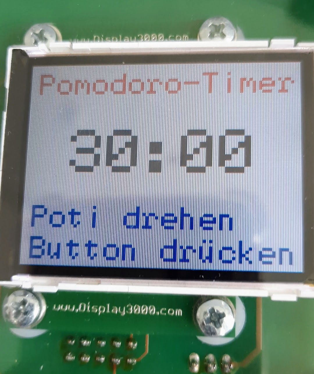
The user is welcomed when the timer is activated and then asked to set a desired timer time between 20 and 120 minutes. The timer can be started by pressing a button. The working phase is announced by a short beep. A red LED signals this phase.
A distance meter shows whether the user is directly in front of the display and concentrating on the actual task. If this is the case, a corresponding message appears. When the work phase is finished, an acoustic signal sounds again and a pause timer of 5 minutes starts. The pause phase is accompanied by a green LED.
Afterwards, you will be asked if you want to set the timer again. It is possible to define a timer time again and start it directly. The process starts again from the beginning. The timer can be cancelled at any time by pressing the second button.
Video
We produced a short video to show the timer in action. Unfortunately, the video is only available in German.
Youtube: https://www.youtube.com/watch?v=HgpEMiuY4Y4
For data protection reasons the video is not embedded, only linked – sorry.
Hardware
The board, a HAW-self development board based on the ATmega 328p together with a suitable display (Display3000), was predetermined by the assignment of the class. The range of sensors we could choose from was also limited. We decided on the following components:
- RGB LED
- Ultrasonic sensor (HC-SR04)
- buttons
- potentiometer
- Active Buzzer as well as some jumpers, resistors and a breadboard.

Conclusion
The project was fun, although it was a lot of work. Many data sheets had to be read and the code often had to be completely restructured to accommodate all the functions. Unfortunately, the ultrasonic sensor didn’t work correctly until we handed it in, so we got a point deduction for that.